Synthetic Aperture RADAR
Synthetic Aperture RADAR (“SAR”), uses mathematical techniques, to combine reflected signal phase and amplitude information, as a function of time, from several adjacent-in-time RADAR pulses to build up (“synthesise”) a high resolution image, matching the quality achievable from a much larger antenna, without any additional mathematical manipulation.
While SAR is often used because of its all-weather, day-or-night capability, it also finds application because it renders a different view of a " target," with synthetic aperture radar being at a much lower electromagnetic frequency than optical sensors.
Miniature Radar Developed for Lightweight Unmanned Aircraft
from http://www.defensenews.com/
By William Matthews, 18 March 2008
A small Utah company has flown a tiny synthetic aperture radar in a small UAV in an effort to bring all-weather surveillance capabilities to long-loitering tactical UAVs.
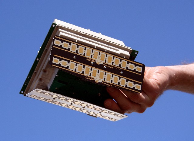
Photograph from http://www.imsar.net/
A two-pound "NanoSAR" radar flew in a ScanEagle UAV over an Oregon test range in January.
The radar - weighing less than one-tenth as much as the smallest standard synthetic aperture radars - promises to give small UAVs the ability to peer through clouds, fog, rain, smoke, sand storms and other conditions that dim the vision of optical and infrared sensors, said Adam Robertson, NanoSAR program manager at ImSAR, a Salem, Utah, radar maker.
The little radar took up about as much space as a shoebox in the 40-pound, 4-foot-long, 10-foot wide UAV, according to Boeing, which is a partner of ImSAR and UAV maker Insitu of Bingen, Wash.
The smallest standard synthetic aperture radars weigh about 30 pounds. Most weigh between 50 and 200 pounds, according to Boeing, making them too big for all but the largest UAVs.
ImSAR was able to dramatically reduce the weight of its radar by using printed circuit board technology in place of the heavy metal tubes that serve as radio wave guides in standard synthetic aperture radars, Robertson said. Etched on fiberglass boards, the radar circuits are similar to the lightweight circuits used in laptop computers and cell phones, he said.
Because of power limits dictated by the circuit boards and the small UAV's restricted power supply, the NanoSAR has a relatively short range. It is intended for tactical use, Robertson said.
The ScanEagle can fly above 16,000 feet and can loiter over a battlefield for more than 24 hours, providing persistent low-altitude reconnaissance, according to Boeing.
Synthetic aperture radars are good at detecting metal objects that are not easily visible to optical or infrared sensors, Robertson said. That makes the NanoSAR good for spotting small vessels at sea despite fog or clouds, and spotting trucks, tanks or other vehicles despite camouflage.
Another benefit: The printed circuit technology makes the NanoSAR much cheaper than standard synthetic aperture radars, Robertson said. The cost difference is nearly as dramatic as the weight difference, he said.
During the January test flight, data collected by the radar was stored in the UAV and converted into images after the UAV landed. The next step in testing, according to Boeing, will be to create imagery from the UAV in real time.
Robertson said the NanoSAR is expected to be in production before the end of 2008.
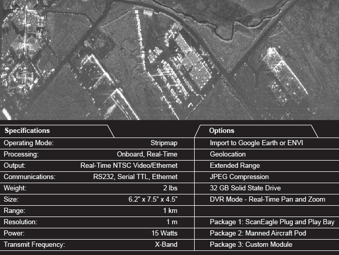
The Sandia National Labs SAR System
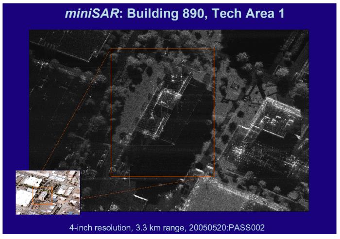
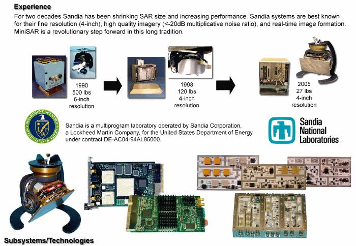
from http://www.sandia.gov/RADAR/images/SAND2005-3445PMiniSAR-fact-sheetp2-v4-redo.pdf
Reconnaissance, Surveillance, and Targeting
Many applications for synthetic aperture radar are for reconnaissance, surveillance and targeting. These applications are driven by the military's need for all-weather, day-and-night imaging sensors. SAR can provide sufficiently high resolution, to distinguish terrain features and to recognize and identify selected man made targets.
Interferometry (3-D SAR, IFSAR)
Interferometric SAR data can be acquired using two antennas on one aircraft, or, by flying two slightly offset passes of an aircraft, with a single antenna. Interferometric SAR can be used to generate very accurate surface profile maps of the terrain, as shown below.
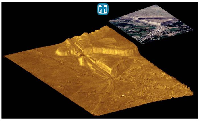
Sandia has developed new mathematical techniques for relating the radar reflection from the terrain surface to the time delay between radar signals received at the two antenna locations. The techniques are directed at removing ambiguities in estimates of surface heights and are referred to as 2-D least squares phase unwrapping.
Navigation and Guidance
Synthetic aperture radar provides the capability for all-weather, autonomous navigation and guidance. By forming SAR reflectivity images of the terrain and then "correlating" the SAR image with a stored reference (obtained from optical photography or a previous SAR image), a navigation update can be obtained. Position accuracies of less than a SAR resolution cell can be obtained. SAR may also be used in guidance applications by pointing or "squinting" the antenna beam in the direction of motion of the airborne platform.
Foliage, Ground and Flame Penetration
Synthetic aperture radars offer the capability for penetrating materials, which are optically opaque and thus not visible by optical or IR techniques. Low-frequency SARs may be used under certain conditions to penetrate foliage and even soil. This provides the capability for imaging targets, normally hidden by trees, brush, and other ground cover. To obtain adequate foliage and soil penetration, SARs must operate at tens of MHz to 1 GHz.
Recent studies have shown that SAR may provide a limited capability for imaging selected underground targets, such as utility lines, bunkers, mines, etc. Depth of penetration varies with soil conditions (moisture content, conductivity, etc.) and target size but individual measurements have shown the capability for detecting 55-gallon drums and power lines at depths of several meters. In dry sand, penetration depths of tens of meters are possible.
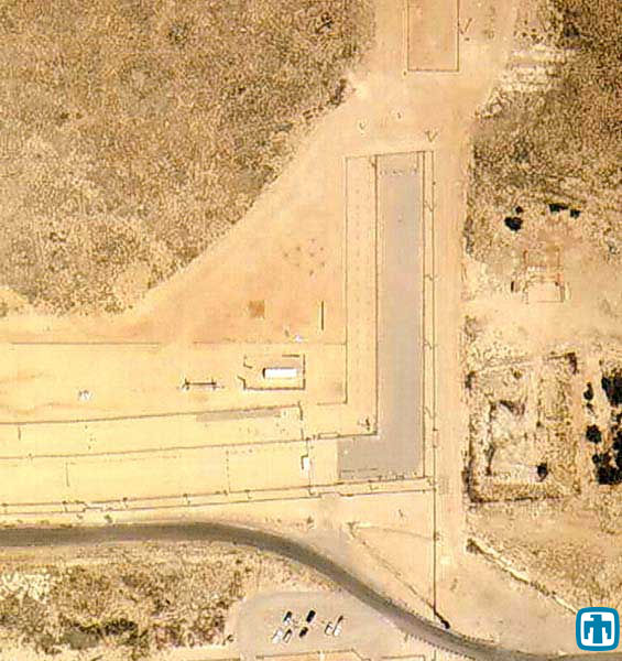
Change Detection
A technique known as coherent change detection offers the capability for detecting changes between imaging passes. (Example: Coherent Change Detection image of vehicle tracks and an optical photo of the same area ) To detect whether or not a change has occurred, two images are taken of the same scene, but at different times. These images are then geometrically registered so that the same target pixels in each image align. After the images are registered, they are cross correlated pixel by pixel.
Where a change has not occurred between the imaging passes, the pixels remain correlated, whereas if a change has occurred, the pixels are uncorrelated. Of course, targets that are not fixed or rigid, such as trees blowing in the wind, will naturally decorrelate and show as having "changed." While this technique is useful for detecting change, it does not measure direction or the magnitude of change.

Environmental Monitoring
SAR is used for a wide variety of environmental applications, such as monitoring crop characteristics, deforestation, ice flows, and oil spills. Oil spills can be detected in SAR imagery because the oil changes the backscatter characteristics of the ocean. Radar backscatter from the ocean results primarily from capillary waves through Bragg scattering (constructive interference from the capillary waves being close to the same wavelength as the SAR). The presence of oil dampens the capillary waves, decreasing the radar backscatter. Thus, oil slicks appear dark in SAR images, relative to oil-free areas.
from www.SANDIA.gov/RADAR
The Brigham-Young University YINSAR system
Remote Sensing: Compact, low-cost synthetic aperture radar
"The design of radar systems suitable for unmanned aerial vehicles represents both advances in technology and acceptable tradeoffs" by David Long
Synthetic aperture radar (SAR) is a powerful remote-sensing tool that can operate independent of solar illumination to produce radar images at night and under cloudy conditions. Using signal-processing techniques to generate high-resolution radar images, SAR systems operate from airborne platforms and spacecraft. Their operating frequency can be customized to enhance target characteristics. For example, low-frequency SAR can penetrate vegetation and dry soils, while high-frequency SAR emphasizes vegetation. Unfortunately, the complexity and high costs of SAR systems often preclude them from applications requiring long-term monitoring or frequent revisiting. Moreover, large size and power requirements have limited SAR to large and expensive platforms. There is a need for small, low-cost, high-resolution SAR systems designed for operation on small unmanned aerial vehicles (UAVs).
Faculty and students at Brigham Young University (BYU) have successfully developed a number of compact, low-cost, low-power SAR systems. These include an interferometric system known as YINSAR and a series of very small, ‘microSAR’ systems designed for operation on small UAVs.
The BYU microSAR design represents a tradeoff between coverage and precision versus cost and size. It is an ultra-low-power system designed for ‘turn on and forget’ operation on a UAV with a 6ft wingspan. The system records data continuously on a pair of compact flash disks for over an hour. Post-flight, the flash disks are loaded onto a laptop and processed into images using SAR image-formation and autofocusing software. Real-time processing and image downlink capability are being developed (see Figure 1 ).
 block diagram.jpg)
Figure 1. Shown is a micro-synthetic aperture radar (microSAR) block diagram.
The microSAR system consists of a stack of 3 × 3.4 × 3in. circuit boards and two flat microstrip antennas, each approximately 4 × 12in. (see Figure 2 ). Minimal enclosures reduce flight weight to less than 2lbs. Power consumption is 16W. With conventional SAR, short pulses are transmitted and separated by a receive interval. In contrast, with microSAR, transmission and receipt occur simultaneously via continuous-wave linear-frequency modulation, enabling low-power operation. To optimize performance, microSAR uses bi-static operation, in which transmission and receipt occur via different antennas. Designed for operation at 300–2500ft and 20–50m/s, microSAR has a swath width of 200–900m with a nominal one-look spatial resolution of ∼ 10 × 60cm, which is multi-look averaged to 1 × 1m in processed imagery. The averaging reduces the ‘speckle noise’ inherent in SAR images. Sample microSAR images are shown in Figure 3 . The first microSAR operated at C-band (5.56GHz), but microSAR systems at other bands have also been built.
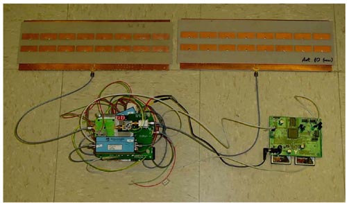
Figure 2. The BYU microSAR system is suited to small unmanned aerial vehicles.
SAR imaging is coherent, using the phase of the radar echo. This can be exploited to infer topography as well as to generate images by combining data from multiple receive antennas separated by a baseline. YINSAR uses two multiple antennas to enable extraction of surface topography from a small six-passenger Cessna 337M Skymaster (see Figure 4 ). Operating at 9.9GHz (X-band), YINSAR employs a 200MHz bandwidth chirp to achieve a single-look resolution of 60 × 10cm and a multi-look resolution of 1 × 1m with 1m height accuracy (see Figures 5 and 6).
Cost was minimized by using a double-sideband (DSB) transmit chirp and an all-digital final intermediate frequency. The DSB chirp doubles the effective bandwidth of the transmit signal with only a small signal-to-noise ratio loss due to reduced carrier suppression. The bi-static antenna system consists of three identical waveguide-fed horn antennas with a baseline length of ∼ 1m. Aircraft altitude and motion data are used to compensate for aircraft motion in the post-flight processing.
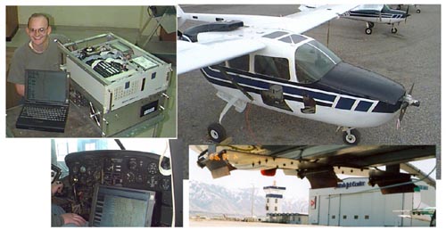
Figure 4. These photographs show (upper left) YINSAR radar hardware (upper right) a Cessna Skymaster platform (lower left) a laptop controller (lower right) 12ft-long antennas mounted under the aircraft.
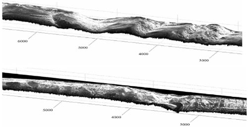
Figure 5. Shown are sample 3D YINSAR images (4 × 47-look SAR magnitude image draped over SAR interferometry-derived topography). Flight direction is right to left, with the near range at the back of the figure.
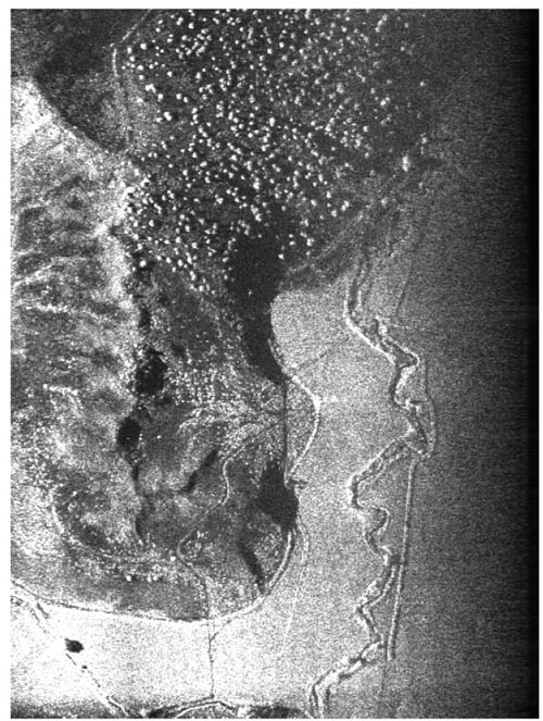
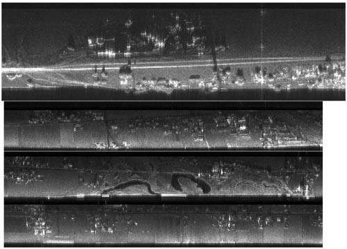
Figure 6. A sample 2D YINSAR image with 1 × 1m resolution shows a vegetated hill surrounded by fields with a creek running through them.
SAR technology at Sandia Labs
from http://www.sandia.gov/RADAR/minicomp.html
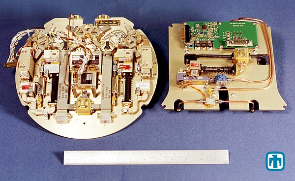
Sandia National Laboratories, with its in-house RF and microwave development capabilities, has designed, fabricated, tested, and integrated a multitude of microwave subsystems to support various synthetic aperture radar programs. Below are several examples of hardware developed at Sandia National Laboratories. Various component realizations and levels of miniaturization are illustrated.
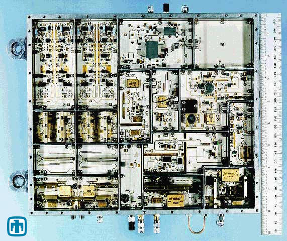
Fully integrated and miniaturized stable local oscillator (STALO), RF upconverter, and dual-channel receiver for Ku-Band (15 GHz) synthetic aperture radar. This RF subassembly illustrates surface-mount hybrid microcircuit (HMC) packaging technology.
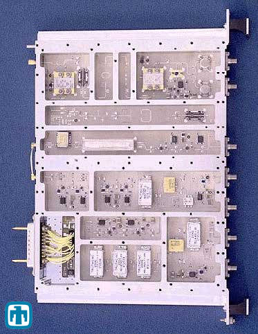
Ku-Band (12.7 GHz) frequency upconverter in a 6U-VME form factor for next-generation modular SAR. The module employs surface mount component technology with microstrip circuitry realized on Rogers TMM ® substrate.
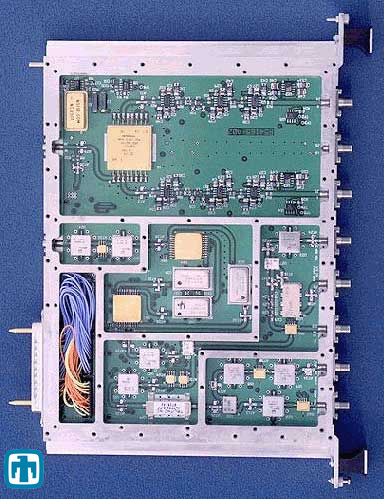
4 GHz IF receiver with dual conversion and quadrature video demodulation for modular SAR systems. The module employs surface mount component technology with microstrip circuitry realized on standard low-cost FR4 substrate.
Ka-band (35 GHz) dual-channel front end microwave assembly.